| Brief Description | |
|---|---|
|
File: \examples\Processing\Trigger\mE4VD4-CL\Line\TrgPortLineRebuild_mE4VD4CL.va |
 |
|
Default Platform: mE4VD4-CL |
|
|
Short Description VisualApplets operator TrgPortLine is rebuild with other signal processing operators from the VisualApplets operator libraries. The rebuild allows you custom trigger functionalities and shows the usage of many signal processing operators in VisualApplets. |
|
Operator TrgPortLine is a complex VisualApplets operator which offers a wide range of line scan trigger functionalities. In some applications it is required to have a modified functionality of this operator for custom signal processing.
In this example, we present a rebuild of the TrgPortLine operator with other VisualApplets signal processing operators. This enables you to adapt and modify the functionality to your custom requirements. The implementation is advanced but easy to understand. To simply the complex parameterization of the implementation, the following translation table helps you to calculate the parameters of the new design based on the parameternames of the TrgPortLine parameters.
| 名称 | YOffset |
|---|---|
| 默认 | 0 |
Device1_Process0_ImageTrigger_ImageHeight_Width = YHeight - YOffset Device1_Process0_ImageTrigger_ImageTriggerDelay_Delay_Delay = YHeight + YOffset |
|
| 名称 | YHeight |
|---|---|
| 默认 | 1024 |
Device1_Process0_ImageTrigger_ImageHeight_Width = YHeight - YOffset Device1_Process0_ImageTrigger_ImageTriggerDelay_Delay_Delay = YHeight + YOffset |
|
| 名称 | LineTriggerMode |
|---|---|
| 默认 | GrabberControlled |
Device1_Process1_LineTrigger_LineTriggerMode_Select = 3 if GrabberController 0,1 or 2 if Extern_Trigger For Extern_Trigger, the correct value is defined by the shaft encoder settings. The other modes available by TrgPortLine are not supported. |
|
| 名称 | ExsyncEnable |
|---|---|
| 默认 | OFF |
Device1_Process1_LineTrigger_Exsync_ExsyncEnable_Select = 1 if ON 0 if OFF |
|
| 名称 | LineTrgInSourceA |
|---|---|
| 默认 | 0 |
Device1_Process1_LineTrigger_TraceA_Input_Select = LineTrgInSourceA |
|
| 名称 | LineTrgInSourceB |
|---|---|
| 默认 | 1 |
Device1_Process1_LineTrigger_TraceB_Input_Select = LineTrgInSourceB |
|
| 名称 | EncoderABMode |
|---|---|
| 默认 | Signal_A_Only |
Device1_Process1_LineTrigger_LineTriggerMode_Select = 3 if LineTriggermode == GrabberControlled 0 if EncoderABMode == Signal_A_Only 1 else Device1_Process1_LineTrigger_ShaftEncoder_Mode = Mode1X if EncoderABMode == Signal_AB_Filter Mode2X if EncoderABMode == Signal_ABx2_Filter Mode4X if EncoderABMode == Signal_ABx4_Filter |
|
| 名称 | EncoderABLead |
|---|---|
| 默认 | Signal_AB |
Device1_Process1_LineTrigger_ShaftEncoder_LeadingTrace = A if EncoderABLead == Signal_AB B else |
|
| 名称 | LineTrgInPolarity |
|---|---|
| 默认 | LowActive |
Device1_Process1_LineTrigger_TraceA_Polarity_Invert = Invert if LineTrgInPolarity = LowActive NotInvert else |
|
| 名称 | LineTrgInPolarity |
|---|---|
| 默认 | LowActive |
Device1_Process1_LineTrigger_TraceA_Polarity_Invert = Invert if LineTrgInPolarity = LowActive NotInvert else Device1_Process1_LineTrigger_TraceB_Polarity_Invert = Invert if LineTrgInPolarity = LowActive NotInvert else |
|
| 名称 | LineTrgDownscaler |
|---|---|
| 默认 | 1 |
Device1_Process1_LineTrigger_Downscale_Donwscale = LineTrgDownscaler |
|
| 名称 | LineTrgPhase |
|---|---|
| 默认 | 1 |
Device1_Process1_LineTrigger_Downscale_SelectecPulse = LineTrgPhase |
|
| 名称 | ExsyncPeriod |
|---|---|
| 默认 | 100µs |
Device1_Process1_LineTrigger_Generate_Period = ExsyncPeriod / TClk |
|
| 名称 | Exsync2Delay | |||
|---|---|---|---|---|
| 默认 | 0µs | |||
Device1_Process1_LineTrigger_Exsync_Exsync2_Delay = Exsync2Delay / TClk
|
||||
![[Note]](../common/images/admon/note.png)
| 名称 | ExsyncPolarity |
|---|---|
| 默认 | LowActive |
Device1_Process1_LineTrigger_Exsync_OutputPolarity_Polarity = Invert if ExsyncPolarity = LiwActive NotInvert else |
|
| 名称 | ImgTriggerMode |
|---|---|
| 默认 | FreeRun |
Device1_Process0_ImageTrigger_SelectGatedImageTrigger_Select = 1 if ImgTriggerMode == FreeRun 0 else Device1_Process0_ImageTrigger_SelectFreeRun_Select = 1 if ImgTriggerMode == FreeRun 0 else |
|
| 名称 | ImgTriggerInSource |
|---|---|
| 默认 | InSignal0 |
Device1_Process0_ImageTrigger_EnableSoftwareTrigger = 1 if ImgTriggerInSource == SoftwareTrigger 0 else Device1_Process0_ImageTrigger_ImageTriggerInput_Input_Select = 0 if ImgTriggerInSource == InSignal0 1 if ImgTriggerInSource == InSignal1 2 if ImgTriggerInSource == InSignal2 3 if ImgTriggerInSource == InSignal3 4 if ImgTriggerInSource == InSignal4 5 if ImgTriggerInSource == InSignal5 6 if ImgTriggerInSource == InSignal6 7 if ImgTriggerInSource == InSignal7 |
|
| 名称 | ImgTrgInPolarity |
|---|---|
| 默认 | LowActive |
Device1_Process0_ImageTrigger_ImageTriggerInput_Polarity_Polarity = Invert if ImgTrgInPolarity == LowActive NotInvert else |
|
| 名称 | ImgTrgDelay | |||
|---|---|---|---|---|
| 默认 | 0 lines | |||
Device1_Process0_ImageTrigger_ImageTriggerDelay_Delay_Delay = ImgTrgDelay
|
||||
| 名称 | FlashEnable |
|---|---|
| 默认 | OFF |
Device1_Process0_ImageTrigger_FlashOutput_Enable_Select = 1 if FlashEnable == ON 0 else |
|
| 名称 | FlashPolarity |
|---|---|
| 默认 | LowActive |
Device1_Process0_ImageTrigger_FlashOutput_Polarity_Polarity = Invert if FlashPolarity == LowActive NotInvert else |
|
| 名称 | FlashDelay | |||
|---|---|---|---|---|
| 默认 | 0 lines | |||
Device1_Process0_ImageTrigger_FlashDelay_Delay_Delay = FlashDelay
|
||||
| 名称 | SoftwareTrgPulse |
|---|---|
Device1_Process0_ImageTrigger_SoftwareTrigger_Mode = Pulse if SoftwareTrgPulse == 1 && ImgTrgMode == ExternSw_Trigger not write access else |
|
| 名称 | SoftwareTrgInput |
|---|---|
Device1_Process0_ImageTrigger_SoftwareTrigger_Mode = High if SoftwareTrgInput == 1 && ImgTrgMode == ExternSw_Gate Low else |
|
| 名称 | ImgTrgIsBusy (read only parameter) |
|---|---|
ImgTrgIsBusy = Device1_Process0_ImageTrigger_ImgTrgIsBusy_Status |
|
| 名称 | CC1output |
|---|---|
| 默认 | Exsync |
Device1_Process1_LineTrigger_Exsync_CC1_Select_Select = 0 if Exsync 1 if ExsyncInvert 2 if Exsync2 3 if Exsync2Invert 4 if Flash 5 if FlashInvert 6 if Gnd 7 if Vcc |
|
| 名称 | CC2output |
|---|---|
| 默认 | Exsync |
Device1_Process1_LineTrigger_Exsync_CC2_Select_Select = 0 if Exsync 1 if ExsyncInvert 2 if Exsync2 3 if Exsync2Invert 4 if Flash 5 if FlashInvert 6 if Gnd 7 if Vcc |
|
| 名称 | CC3output |
|---|---|
| 默认 | Exsync |
Device1_Process1_LineTrigger_Exsync_CC3_Select_Select = 0 if Exsync 1 if ExsyncInvert 2 if Exsync2 3 if Exsync2Invert 4 if Flash 5 if FlashInvert 6 if Gnd 7 if Vcc |
|
| 名称 | CC4output |
|---|---|
| 默认 | Exsync |
Device1_Process1_LineTrigger_Exsync_CC4_Select_Select = 0 if Exsync 1 if ExsyncInvert 2 if Exsync2 3 if Exsync2Invert 4 if Flash 5 if FlashInvert 6 if Gnd 7 if Vcc |
|
| 名称 | ImgTrgDebounceMaxTime |
|---|---|
| Not Required in this implementation. | |
| 名称 | ImgTrgDebouncingTime |
|---|---|
| 默认 | 65.520µs |
Device1_Process0_ImageTrigger_ImageTriggerInput_Debounce_Debounce = ImgTrgDebouncingTime / TClk |
|
| 名称 | LineTrgDebouncingTime |
|---|---|
| 默认 | 0.112µs |
Device1_Process1_LineTrigger_TraceA_Debounce_Debounce = LineTrgDebouncingTime / TClk Device1_Process1_LineTrigger_TraceB_Debounce_Debounce = LineTrgDebouncingTime / TClk |
|
The variable TClk depends on the frame grabber used. For the microEnable IV VD4-CL, the period is 16ns. Check Appendix. Device Resources for a complete list.
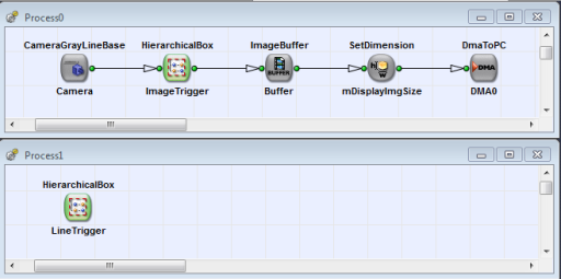
The implementation is divided into the two parts ImageTrigger and LineTrigger. The LineTrigger implementation is located in Process1. As this process has no DMA channel, it will be immediately started after loading the applet to the frame grabber even when the acquisition is not started, yet. This has the advantage, that the camera can already be triggered before the acquisition is started. See 'Processes without DMAs / Trigger Processes' for more information on processes without DMA channels.
The next two sections will outline the implementations of the image trigger and line trigger.
The image trigger part is responsible to assemble the image i.e. to form 2D images from the 1D input line stream. In accordance to operator TrgPortLine the image height can be defined by either a fixed height and usage of all input lines (free run), a fixed height but external controller image start (external or software trigger) or the height can be defined by the pulse length of an external or software trigger signal (gated mode).
The main part of the image trigger implementation is the SignalGate operator. The image height is defined by the time the gate is open. Module ImageHeight (operator SignalWidth) defines the height in the free run or edge controlled trigger modes. In these cases, the operator value is increases with every new input line. This is a good example where the Tick input is used for controlling the counting speed. In the free run mode, a new image is started immediately after the previous one is finished i.e. the SignalWidth operator is finished with the output of its period. In the external or software trigger mode, a new image is started with a rising edge at the input of the SignalWidth. The RS-FF is required to ensure a sufficiently long enough pulse.
With SelectGatedImageTrigger the implementation can be switched to the gated mode, where the pulse length controls the image height.
The hierarchical box NOP_DelayChain includes some NOP operators. These operators are required to delay the input signal a few clock cycles. This is required as the calculation weather the gate has to be opened or closes requires some clock cycles. VisualApplets cannot perform an automated pipeline adjustment in this case. Therefore the delay is required.
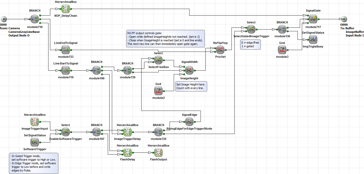
Other parst of the implementation comprise the input output output signal generation. The implementation of these parts is simple and straight forward. The flash output signal is transfered to Process1 using a TxSignalLine operator in h-box FlashOutput. This is required as the flash signal has to be output to the CC signals as well.
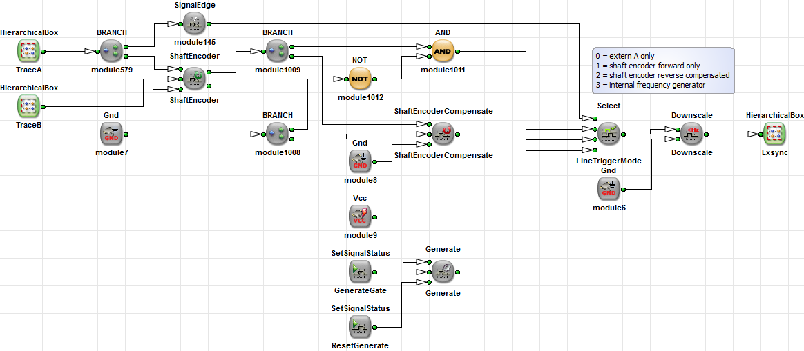
The LineTrigger hierarchical box mainly consists of the input and output signal generation as well as the shaft encoder analysis and frequency generator. For the shaft encoder signal analysis operators ShaftEncoder, ShaftEncoderCompensate are used. The Select switch LineTriggerMode allows for an individual selection if the compensation or two trance analysis is enabled or disabled. Moreover, an internal frequency generator represented by a Generate operator is implemented to trigger the camera.